Hyundai Genesis (DH): Smart Cruise Control System / Smart Cruise Control Unit Schematic Diagrams
| Circuit Diagram |
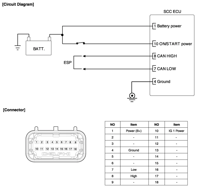
Specification ItemSpecificationPower supply(V)12Operation voltage (V)9 ~ 16
Removal 1. Remove the bumper. (Refer to Body - "Front Bumper") 2. Disconnect the smart cruise control unit connector. 3. Remove the smart cruise control unit assembly (A) from vehicle after loosening mounting bolts.
Other information:
Hyundai Genesis (DH) 2013-2016 Service Manual: Photo Sensor Repair procedures
Inspection 1. Turn the ignition switch ON. 2. Connect the GDS. 3. Emit intensive light toward the photo sensor using a lamp, and check the output voltage change. 4. The voltage will rise with higher intensive light and fall with lower intensive light.
Hyundai Genesis (DH) 2013-2016 Service Manual: Power Mosfet Repair procedures
Inspection 1. Turn the ignition switch ON. 2. Manually operate the control switch and control the voltage of the blower motor. 3. Select the control switch to raise the voltage until high speed. Specification Fan Speed (Manual)Motor Voltage (V)13.
Categories
- Manuals Home
- Hyundai Genesis Owners Manual
- Hyundai Genesis Service Manual
- Emission Control System
- Body (Interior and Exterior)
- Repair procedures
- New on site
- Most important about car
