Hyundai Genesis: AVN System / Speaker Repair procedures
Hyundai Genesis (DH) 2013-2016 Service Manual / Body Electrical System / AVN System / Speaker Repair procedures
| Inspection |
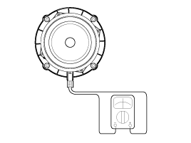
| Troubleshooting of the speakers |
When handling the speakers:
|
| 1. |
Basic inspection
Loosen the screws to rule out the interference from the body trims and surrounding parts and then remove the speaker.
After removing the speaker, check the sound quality of the speaker with the connector plugged in. |
| 2. |
Inspection for each cause
|
| Removal |
Front door speakers
| 1. |
Disconnect the negative (-) battery terminal. |
| 2. |
Remove the front door trim. |
| 3. |
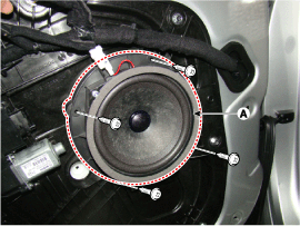
Remove the front speaker (A) after loosening the screws.
(Refer to Body - "Front Door Trim")
|
| 4. |
Remove the twitter speakers (A) after loosening the screws.
|
Rear door speakers
| 1. |
Disconnect the negative (-) battery terminal. |
| 2. |
Remove the Rear door trim.
(Refer to Body - "Rear Door Trim") |
| 3. |
Remove the rear speakers (A),(B) after loosening the screws.
|
| 4. |
Remove the twitter speakers (A) after loosening the screws.
|
Crash pad center speaker
Take care not to scratch the crash pad and related parts. |
| 1. |
Disconnect the negative (-) battery terminal. |
| 2. |
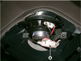
Using a scraper or remover, remove the crash pad center speaker cover.
|
| 3. |
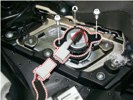
After loosening the connector and screws, remove the center speaker (A).
|
Sub Woofer Speaker
| 1. |
Disconnect the negative (-) battery terminal. |
| 2. |
Remove the rear seat.
(Refer to Body - "Rear Seat") |
| 3. |
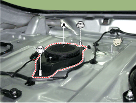
Remove the rear package tray (A).
(Refer to Body - "Rear Seat")
|
| 4. |
Remove the sub woofer speaker (A) after removing bolts (4EA). |
Surround Speaker
| 1. |
Disconnect the negative (-) battery terminal. |
| 2. |
Remove the rear seat.
(Refer to Body - "Rear Seat") |
| 3. |
Remove the rear package tray (A).
(Refer to Body - "Rear Seat")
|
| 4. |
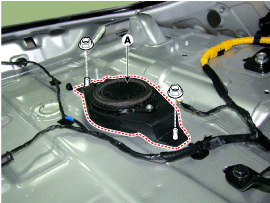
Remove the surround speaker (A) after removing screws (2EA).
|
Midrange Speaker (Crash Pad)
| 1. |
Disconnect the negative (-) battery terminal. |
| 2. |
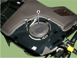
Remove the left/right crash pad side speaker grille (A
|
| 3. |
Remove the midrange speaker (A) after removing the connector and screws.
|
| Installation |
Front Door Speaker
| 1. |
Install the front door speaker. |
| 2. |
Install the front door trim. |
Midrange Speaker (Crash Pad)
| 1. |
Install the midrange speaker |
| 2. |
Install the crash pad side speaker grille. |
| 3. |
Connect the negative (-) battery terminal. |
Rear Door Speaker
| 1. |
Install the rear door speaker. |
| 2. |
Install the rear door trim. |
Crash Pad Center Speaker
| 1. |
Install the center speaker. |
| 2. |
Install the center speaker grille. |
Subwoofer Speaker
| 1. |
Install the subwoofer speaker. |
| 2. |
Install the rear package tray and rear seat. |
Surround Speaker
| 1. |
Install the surround speaker. |
| 2. |
Install the rear package tray and rear seat. |
Make sure the speaker connectors are plugged in properly. |
 AVN Antenna Repair procedures
Inspection
Glass Antenna Test
1.
Wrap aluminum foil (A) around the tip of the tester probe (B)
and move the probe along the grid line to check whether the circuit
opens.
2.
Bring one end ...
 AUX jack Schematic Diagrams
Circuit Diagram
...
Other information:
Hyundai Genesis (DH) 2013-2016 Service Manual: Transmission Control Module (TCM) Schematic Diagrams
1. TCM Connector and Terminal Function 2. TCM Terminal Function Connector PinDescriptionPinDescription1Battery power48-2Battery power49-3Power(IG 1)5027 Brake control solenoid valve4Ground51-5Ground52ON/OFF solenoid valve6Ground53-7-54Input speed sensor signal8-55Middle speed sensor signal9-5 ...
Hyundai Genesis (DH) 2013-2016 Owners Manual: Head Up Display (HUD)
Description The head up display is a transparent display which projects a shadow of some information of the instrument cluster and navigation on the windshield glass. The head up display image on the windshield glass may be invisible when: - Sitting posture is bad. - Weari ...
© 2013-2025 www.hgenesisdh.com


