Hyundai Genesis (DH): Fuses And Relays / Relay Box (Engine Compartment) Repair procedures
Hyundai Genesis (DH) 2013-2016 Service Manual / Body Electrical System / Fuses And Relays / Relay Box (Engine Compartment) Repair procedures
| Inspection |
| 1. |
Disconnect the negative (-) battery terminal. |
| 2. |
Pull out the relay from the engine compartment relay box. |
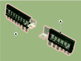
Power Relay (Type A)
Check for continuity between the terminals.
A : start relay
| 1. |
After supplying power to between No. 85 and 86 power relay
terminals, check that there is continuity between No. 30 and 87
terminals. |
| 2. |
After disconnecting power between No. 85 and 86 power relay
terminals, check that there is no continuity between No. 30 and 87
terminals.
Engine Room Relay Box
Diesel Box
|


Power Relay (Type B)
Check for continuity between the terminals.
A : Cooling fan relay
| 1. |
After supplying power to between No. 85 and 86 power relay
terminals, check that there is continuity between No. 30 and 87
terminals. |
| 2. |
After disconnecting power between No. 85 and 86 power relay
terminals, check that there is no continuity between No. 30 and 87
terminals.
|


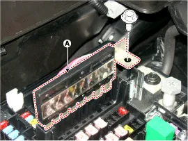
Metal Core PCB block
| 1. |
Disconnect the battery(-) terminals. |
| 2. |
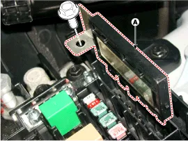
Push the four hooks in the direction of the arrow and lift up the metal core PCB block (A).
|

| 3. |
Remove the metal core PCB by disconnecting the connector. |
Fuse
| 1. |
Check that the fuse holders are loosely held and that the fuses are securely fixed by the holders. |
| 2. |
Check that each fuse circuit has the exact fuse capacity. |
| 3. |
Check the fuses for any damage.
|

Multi Fuse
Engine room fuse is to optimize the package.
|

Component Location Engine room junction block Battery junction block
Component Location Interior Junction Block
Other information:
Hyundai Genesis (DH) 2013-2016 Service Manual: Troubleshooting
Troubleshooting Problem Symptoms Table Before replacing or repairing air conditioning components, first determine if the malfunction is due to the refrigerant charge, air flow or compressor. Use the table below to help you find the cause of the problem.
Hyundai Genesis (DH) 2013-2016 Service Manual: Photo Sensor Description and Operation
Description The photo sensor is located in the right side of the inside rearview mirror. he integrated rain sensor is located in the right side of the inside rearview mirror. The integrated rain sensor is a multifunctional sensor which combines the photo sensor and auto light sensor, and has a built-in photovoltaic diode (for detecting t
Categories
- Manuals Home
- Hyundai Genesis Owners Manual
- Hyundai Genesis Service Manual
- Restraint
- Body Electrical System
- Body (Interior and Exterior)
- New on site
- Most important about car

Copyright © 2026 www.hgenesisdh.com - 0.0197