Hyundai Genesis (DH): Parking Guide System (PGS) / PGS Unit (Back & Blinde Unit) Components and Components Location
| Components |
Description Control Function This system supports 2 kinds of main function. (Rear video display function, Expected trace of wheels display function) The Rear video display and the expected trace of wheels display operate according to Vehicle speed condition and Gear position.
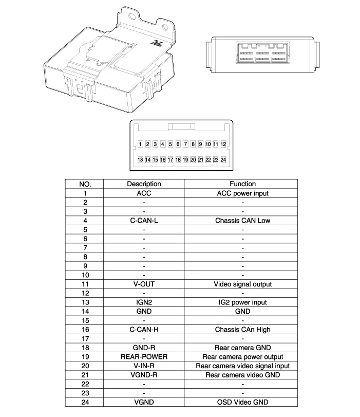
Circuit Diagram Input / Output Terminal Voltage No.SignalDescriptionlevel1ACCACCOFF(Less than 1V), ON(More than 8V)4C-CAN-LHigh Speed CAN low-11V-OUTVideo Out-13IGNIGN SignalON(More than 9V) / OFF(Less than 1V)16C-CAN-HHigh Speed CAN high-18GND-RRear Camera GND-19REAR-POWERVCC-REARON(6~7V) / OFF(Less than 1V)20V-IN-RRear Video Input-20VGND-RRear Video Gnd-22SERIAL LINETop View Control-24VGNDVideo Out GND-
Other information:
Hyundai Genesis (DH) 2013-2016 Service Manual: Components and Components Location
C
Hyundai Genesis (DH) 2013-2016 Service Manual: Description and Operation
Description Integrated Rain Sensor Integrated rain sensor (A) controls three systems: front wiper, auto-light, and central air conditioner. 1. Wiper Control System When "AUTO" switch signal is received from the multi-function switch on the right, the integrated rain sensor detects the amount of rainfall.
Categories
- Manuals Home
- Hyundai Genesis Owners Manual
- Hyundai Genesis Service Manual
- Emission Control System
- Front Door
- Restraint
- New on site
- Most important about car
