Hyundai Genesis (DH): Panorama Sunroof / Panorama Sunroof Switch Components and Components Location
Hyundai Genesis (DH) 2013-2016 Service Manual / Body Electrical System / Panorama Sunroof / Panorama Sunroof Switch Components and Components Location
| Components |
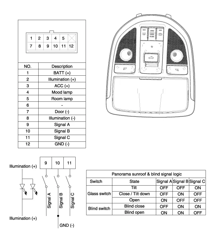
Circuit Diagram NO.Overhead console connector (10pin)Panorama sunroof motor (12pin)Roller blind motor (12pin)1GroundGround 1Battery (+)2-Glass status signal/ Parameter tool-3IGNGNDGround4Signal C switchLIN 1LIN 15Signal A switchLIN2LIN 26Battery (+)Signal B switch-7Glass status signal/ Parameter toolSignal C switch-8Vehicle speed signalSignal A switch-9---10Signal B switch--11?Vehicle speed signal-12IGNIGN
Inspection 1. Disconnect the negative (-) battery terminal. 2. Open the sunglass case cover from the overhead console and remove the 2 screws holding the overhead console.
Categories
- Manuals Home
- Hyundai Genesis Owners Manual
- Hyundai Genesis Service Manual
- Description and Operation
- 4 Wheel Drive (AWD) System
- Engine Mechanical System
- New on site
- Most important about car

Copyright © 2026 www.hgenesisdh.com - 0.0355