Hyundai Genesis (DH): Indicators And Gauges / Instrument Cluster Components and Components Location
Hyundai Genesis (DH) 2013-2016 Service Manual / Body Electrical System / Indicators And Gauges / Instrument Cluster Components and Components Location
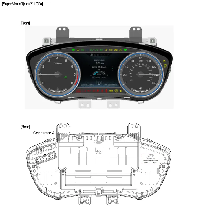
| Components |

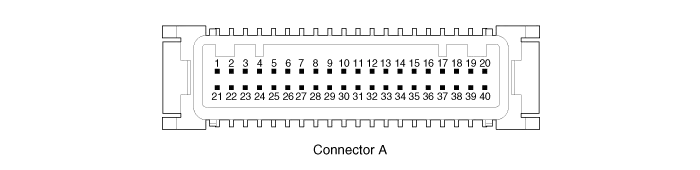
Connector Pin Information
| No. | Description | No. | Description |
| 1 | - | 21 | - |
| 2 | Illumination output | 22 | - |
| 3 | Rheostat down switch | 23 | 4P output |
| 4 | Rheostat up switch | 24 | Immobilizer |
| 5 | AT N output | 25 | AT S output |
| 6 | Oil pressure | 26 | AT R output |
| 7 | Low washer | 27 | AT P output |
| 8 | Charge | 28 | - |
| 9 | AT D output | 29 | - |
| 10 | Illumination + | 30 | MM_CAN High |
| 11 | - | 31 | MM_CAN Low |
| 12 | Active ECO | 32 | C_CAN High |
| 13 | Heated wheel indicator | 33 | C_CAN Low |
| 14 | Fuel | 34 | Trip switch1 |
| 15 | Detent output | 35 | Trip switch2 |
| 16 | Fuel ground | 36 | Trip switch ground |
| 17 | - | 37 | Signal ground |
| 18 | Speaker - | 38 | - |
| 19 | Speaker + | 39 | IGN + |
| 20 | Aig bag + | 40 | Battery + |
Circuit Diagram
Other information:
Hyundai Genesis (DH) 2013-2016 Service Manual: Blind Spot Detection Indicator Components and Components Location
C
Hyundai Genesis (DH) 2013-2016 Service Manual: Power Mosfet Repair procedures
Inspection 1. Turn the ignition switch ON. 2. Manually operate the control switch and control the voltage of the blower motor. 3. Select the control switch to raise the voltage until high speed. Specification Fan Speed (Manual)Motor Voltage (V)13.
Categories
- Manuals Home
- Hyundai Genesis Owners Manual
- Hyundai Genesis Service Manual
- Suspension System
- Brake System
- Steering System
- New on site
- Most important about car

Copyright © 2025 www.hgenesisdh.com - 0.0408