Hyundai Genesis (DH): Engine Control System / Injector Schematic Diagrams
Hyundai Genesis (DH) 2013-2016 Service Manual / Engine Control / Fuel System / Engine Control System / Injector Schematic Diagrams
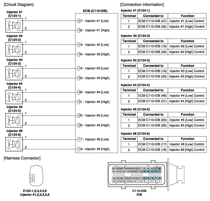
| Circuit Diagram |
Signal Waveform
Inspection 1. Turn the ignition switch OFF. 2. Disconnect the injector connector. 3. Measure resistance between the injector terminals 1 and 2.
Other information:
Hyundai Genesis (DH) 2013-2016 Service Manual: LKAS Unit Repair procedures
Removal 1. Disconnect the negative (-) battery terminal. 2. Remove the mirror wiring cover (A) and rain sensor cover (B). 3. Remove the LKAS unit connector (A). 4. Remove the LKAS unit after disengaging the mounting bracket (A). Installation 1.
Hyundai Genesis (DH) 2013-2016 Service Manual: Ambient Temperature Sensor Repair procedures
I
Categories
- Manuals Home
- Hyundai Genesis Owners Manual
- Hyundai Genesis Service Manual
- Suspension System
- Description and Operation
- Engine Mechanical System
- New on site
- Most important about car

Copyright © 2026 www.hgenesisdh.com - 0.0213