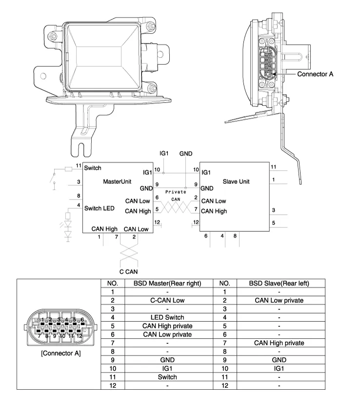
Hyundai Genesis (DH): Blind Spot Detection system / Blind Spot Detection Unit Schematic Diagrams
| Circuit Diagram |
Diagnosis With GDS 1. BSD system defects can be quickly diagnosed with the GDS. GDS operates actuator quickly to monitor, input/output value and self diagnosis.
Removal 1. Disconnect the negative (-) battery terminal. 2. Remove the rear bumper. (Refer to Body - "Rear Bumper") 3. Remove the BSD unit (A) after loosening the mounting nuts.
Other information:
Hyundai Genesis (DH) 2013-2016 Service Manual: Auto Light Sensor Repair procedures
Removal 1. Disconnect the negative (-) battery terminal. 2. Remove the photo & auto light sensor. (Refer to Windshield Wiper/Washer - "Rain Sensor") Installation 1. Install the auto light sensor. 2. Connect the negative (-) battery terminal.
Hyundai Genesis (DH) 2013-2016 Service Manual: In-car Sensor Description and Operation
Description An in-car air temperature sensor is located in the crash pad lower panel. The sensor contains a thermistor which measures the temperature of the cabin. The signal determined by the resistance value which changes in accordance with perceived inside temperature, is delivered to the heater control unit and according to this signa
Categories
- Manuals Home
- Hyundai Genesis Owners Manual
- Hyundai Genesis Service Manual
- Body (Interior and Exterior)
- Description and Operation
- Restraint
- New on site
- Most important about car
