Hyundai Genesis (DH): Lighting System / Rheostat Components and Components Location
Hyundai Genesis (DH) 2013-2016 Service Manual / Body Electrical System / Lighting System / Rheostat Components and Components Location
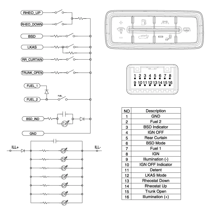
| Components |
Inspection 1. Check for continuity between terminals. If the continuity is not as specified, replace the hazard lamp switch. No.Description1BAT (+)2Illumination (+)3-4Signal5Pilot lamp6-7Illumination (-)8GND Removal
Inspection 1. Disconnect the negative (-) battery terminal. 2. Remove the crash pad lower panel. (Refer to Body - "Crash Pad Lower Panel") 3.
Other information:
Hyundai Genesis (DH) 2013-2016 Service Manual: LKAS Unit Repair procedures
Removal 1. Disconnect the negative (-) battery terminal. 2. Remove the mirror wiring cover (A) and rain sensor cover (B). 3. Remove the LKAS unit connector (A). 4. Remove the LKAS unit after disengaging the mounting bracket (A). Installation 1.
Hyundai Genesis (DH) 2013-2016 Service Manual: Auto Defogging Sensor Repair procedures
R
Categories
- Manuals Home
- Hyundai Genesis Owners Manual
- Hyundai Genesis Service Manual
- Smart Cruise Control Unit Repair procedures
- General Information
- 4 Wheel Drive (AWD) System
- New on site
- Most important about car

Copyright © 2026 www.hgenesisdh.com - 0.0245