Hyundai Genesis (DH): Engine Control System / Rail Pressure Sensor (RPS) Schematic Diagrams
Hyundai Genesis (DH) 2013-2016 Service Manual / Engine Control / Fuel System / Engine Control System / Rail Pressure Sensor (RPS) Schematic Diagrams
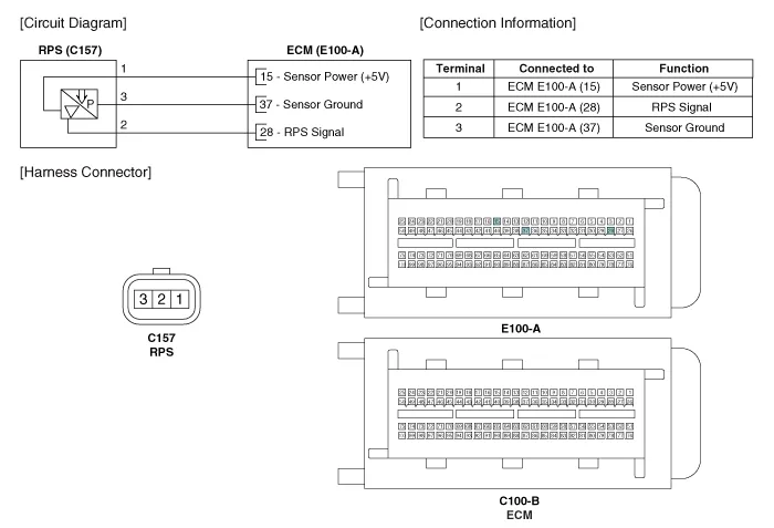
| Circuit Diagram |
Signal Waveform
Inspection 1. Connect the GDS on the Data Link Connector (DLC). 2. Measure the output voltage of the RPS at idle and various engine speed. ConditionOutput Voltage (V)Idle Approx.
Categories
- Manuals Home
- Hyundai Genesis Owners Manual
- Hyundai Genesis Service Manual
- Electric Parking Brake (EPB) Repair procedures
- General Information
- Repair procedures
- New on site
- Most important about car

Copyright © 2026 www.hgenesisdh.com - 0.0238