Hyundai Genesis (DH): Engine Control System / Fuel Tank Pressure Sensor (FTPS) Schematic Diagrams
Hyundai Genesis (DH) 2013-2016 Service Manual / Engine Control / Fuel System / Engine Control System / Fuel Tank Pressure Sensor (FTPS) Schematic Diagrams
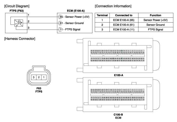
| Circuit Diagram |
Specifications Pressure [kPa (kgf/cm?, in H2O)Output Voltage (V)'-6.67 (-0.068, -26.8)0.502.5'+6.67 (0.068, 26.8)4.5
Inspection 1. Connect the GDS on the Data Link Connector (DLC ). 2. Measure the output voltage of the FTPS. Specification: Refer to "Specification" Removal 1.
Other information:
Hyundai Genesis (DH) 2013-2016 Service Manual: Components and Components Location
C
Hyundai Genesis (DH) 2013-2016 Service Manual: Head Up Display Unit Repair procedures
Removal 1. Disconnect the negative (-) battery terminal. 2. Remove the head up display bezel (A). 3. Remove the instrument cluster. (Refer to Indicators And Guages - "Instrument Cluster") 4. Remove the head up display unit bracket (A) after loosening the mounting nuts.
Categories
- Manuals Home
- Hyundai Genesis Owners Manual
- Hyundai Genesis Service Manual
- Brake System
- Emission Control System
- Parking Assist Sensor Repair procedures
- New on site
- Most important about car

Copyright © 2026 www.hgenesisdh.com - 0.0304