Hyundai Genesis: Engine Control System / ETC (Electronic Throttle Control) System Repair procedures
Hyundai Genesis (DH) 2013-2016 Service Manual / Engine Control / Fuel System / Engine Control System / ETC (Electronic Throttle Control) System Repair procedures
| Inspection |
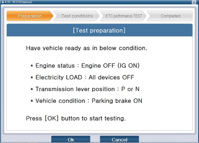
If idle rpm is unstable or engine stops, check the ETC module operation with GDS diagnostic tool.
And if necessary, clean carbon in the throttle body.
| 1. |
Connect the GDS to the Data Link Connector (DLC). |
| 2. |
Select "Vehicle S/W management" > "Inspection / Test" > "ETC Performance Test" on the GDS menu. |
| 3. |
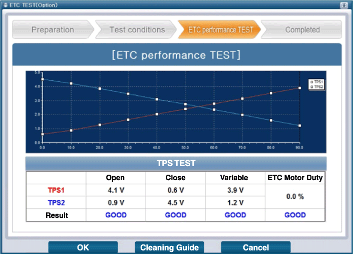
Perform "ETC module test" procedure in accordance with the message.
|
| 4. |
If the test result of the ETC module or TPS signal shows NG, perform ETC module cleaning.
|
| Removal |
| 1. |
Turn the ignition switch OFF and disconnect the battery negative (-) cable. |
| 2. |
Remove the air intake hose.
(Refer to Engine Mechanical System - "Intake AndExhaust System") |
| 3. |
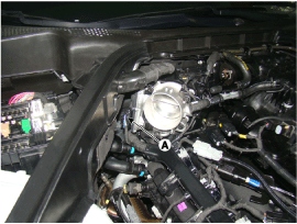
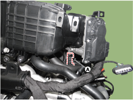
Disconnect the ETC module connector (A).
|
| 4. |
Disconnect the coolant hose (A).
|
| 5. |
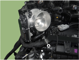
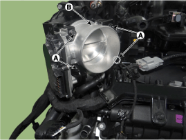
Remove the ETC module (B) from the engine after loosening the installation bolt (A).
|
| Cleaning |
| 1. |
Remove the ETC module.
(Refer to Engine Control System - "ETC Module".) |
| 2. |
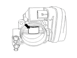
Keep the opening position of the ETC module plate with the fixing jig.
|
| 3. |
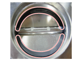
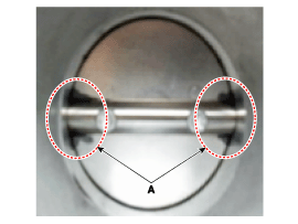
Clean the contamination part of the throttle body with a soft
and lint-free cloth dampened with cleanser to prevent foreign objects
from going in.
|
| 4. |
After cleaning it, re-install the ETC module and perform ETC module learning procedure.
(Refer to Engine Control System - "ETC Module Adjustment".)
|
| Installation |
|
When cleaning the throttle body, clean the valve and carbon at the bore with the cloth wet with the cleaner. |
Do not spray the engine cleaner on the throttle body. |
Be careful that fingers or cloth are not caught in the valve.
When installing the throttle body, make sure that foreign materials do not enter the throttle body.
|
| 1. |
To install, reverse the removal procedure.
|
| Adjustment |
| ETC module learning procedure |
When replacing new ETC module or re-installing it, ETC module learning procedure must be performed.
| 1. |
Hold the ignition key or the start button at the IG ON position for 1 minute. |
| 2. |
After starting the engine, keep the idle state for 15 minutes. |
| 3. |
Turn the ignition key or the start button off and hold for 1 minute. |
| 4. |
Re-start the engine and check the idle roughness. |
Related DTC codes might be displayed if ETC module learning procedure is not performed after replacing ETC module. |
 ETC (Electronic Throttle Control) System Schematic Diagrams
Circuit Diagram
...
 Barometric Pressure Sensor (BPS) Description and Operation
Description
Barometric Pressure Sensor (BPS) is a speed-density type
sensor and is installed on the air cleaner assembly. It senses absolute
pressure of the air cleaner assembly and transfers t ...
Other information:
Hyundai Genesis (DH) 2013-2016 Service Manual: Troubleshooting
Troubleshooting SymptomSuspect AreaEngine does not start or is hard to startVapor hose damaged or disconnectedEEngine struggles to startMalfunction of the purge control solenoid valveRough idle or engine stallsVapor hose damaged or disconnectedMalfunction of the PCV valveRough idleMalfunction o ...
Hyundai Genesis (DH) 2013-2016 Service Manual: Specifications
Specifications Memory power seat unit Item SpecificationsRated voltageDC 12VOperating VoltageDC 9V ~ 16VOperating Temperature Range-30°C ~ 75°C Dark currentMax. 1? Memory power seat switch Item SpecificationsRated voltageDC 5VType Soft Feeling Tact typeOperating Temperature Range-30°C ~ ...
© 2013-2025 www.hgenesisdh.com

