Hyundai Genesis (DH): Lubrication System / Engine Oil Flow Diagram
Hyundai Genesis (DH) 2013-2016 Service Manual / Engine Mechanical System / Lubrication System / Engine Oil Flow Diagram
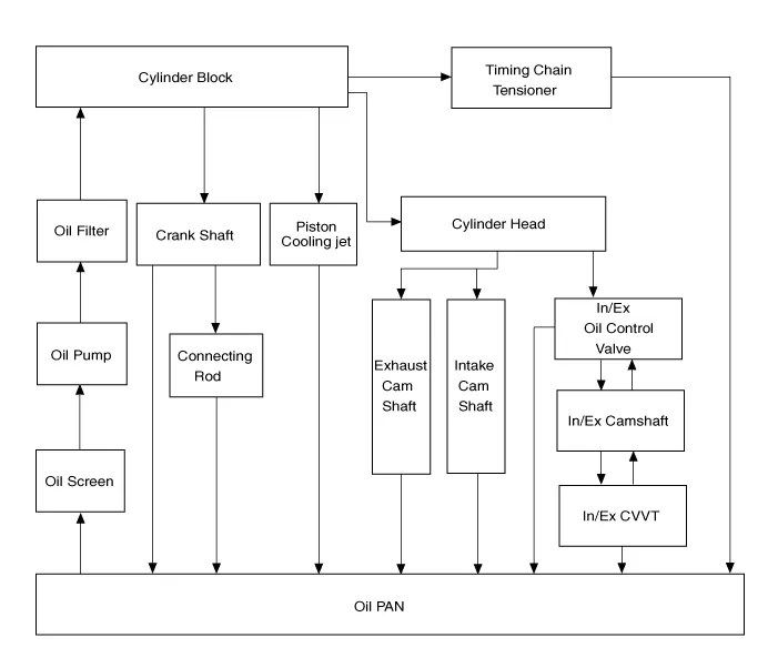
| Engine oil flow diagram |
Replacement
Components 1. Oil filter cap2. O-ring3. Oil filter element4. Oil filter body5. Oil seal
Other information:
Hyundai Genesis (DH) 2013-2016 Service Manual: Description and Operation
Description BSD is a system that measures the speed of and distance from the following vehicles by using two magnetic wave radar sensors attached to the rear bumper, and detects any vehicle within the blind spot zone and gives off alarm (visual and auditory).
Hyundai Genesis (DH) 2013-2016 Service Manual: Blind Spot Detection Switch Repair procedures
Removal 1. Disconnect the negative (-) battery terminal. 2. Remove the crash pad lower panel. (Refer to Body - "Crash Pad") 3. Remove the blind spot detection (BSD) switch (A) after disengaging the mounting clip. Installation 1. Install the crash pad side switch assembly after connecting the connector.
Categories
- Manuals Home
- Hyundai Genesis Owners Manual
- Hyundai Genesis Service Manual
- Brake System
- Restraint
- Smart Cruise Control Unit Repair procedures
- New on site
- Most important about car

Copyright © 2026 www.hgenesisdh.com - 0.0252