Hyundai Genesis (DH): Engine Control System / Accelerator Position Sensor (APS) Schematic Diagrams
| Circuit Diagram |
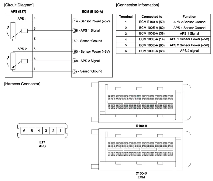
Specification AcceleratorPositionOutput Voltage (V)APS1APS2C.T0.7 ~ 0.80.33 ~ 0.43W.O.T3.85 ~ 4.351.93 ~ 2.18
Inspection 1. Connect the GDS on the Data Link Connector (DLC). 2. Turn the ignition switch ON. 3. Measure the output voltage of the APS 1 and 2 at C.
Other information:
Hyundai Genesis (DH) 2013-2016 Service Manual: Refrigerant Line Repair procedures
Replacement 1. Discharge refrigerant from refrigeration system. 2. Replace any faulty tubes or hoses. Cap the open fittings immediately to keep moisture or dirt out of the system. 3. Tighten the bolt or nut joint to the specified torque.
Hyundai Genesis (DH) 2013-2016 Service Manual: Ambient Temperature Sensor Description and Operation
Description The ambient temperature sensor is located inside the side mirror and detects ambient air temperature. It is a negative type thermistor; resistance will increase with lower temperature, and decrease with higher temperature. The sensor output will be used for discharge temperature control, temperature regulation door control,
Categories
- Manuals Home
- Hyundai Genesis Owners Manual
- Hyundai Genesis Service Manual
- Engine Electrical System
- Engine Control / Fuel System
- Steering System
- New on site
- Most important about car
